

Capacitor
A
capacitor is an electrical component capable to store electrical energy in the
form of voltage existing across it. The voltage applied across the capacitor
sets up an electric field in it and energy is stored in the electric field.
Various capacitors are shown in Fig. 1.

Fig.
1 Various Capacitors
Capacitor
consists of two conducting plates separated by insulating (non-conducting) or
dielectric material when the voltage is applied across the two plates it stores
the voltage in the form of electric field, as one plate becomes positive
charged plate correspondingly other plate becomes negative charged and it
releases energy when load is connected across it at the other side. Capacitance
is the ability of capacitor to store charge measured generally in micro Farads
(µF) and pico Farad (pF).
A capacitor offers low impedance to ac
(alternating current) and high impedance to dc (direct current) means it easily
allow ac to pass through it but at the same time it blocks dc.
Capacitors
are used for waveform generation, filtering, bypassing and blocking
applications. They are used in ICs like integrators, differentiators, and in
many wave shaping circuits and in TV remote control and radio also we can see
the direct use of it.
Capacitor
can be fixed capacitor or variable capacitor. Variable capacitors are mostly
air-gang capacitors which are used in radio telecast work. Symbolic
representation of capacitors are shown in Fig. 2.

Fig.
2 Symbolic representation of Fixed and Variable Capacitors
Types
of Capacitor- Capacitors are categorized based on
insulating material used as
1. Mica
capacitors
2. Paper
capacitors
3. Plastic
film capacitors
4. Electrolytic
capacitors
5. Non
polarized capacitors
6. Ceramic
capacitors
1.
Mica
Capacitors- Mica capacitors are constructed by
sandwiching mica with metal foil. Fig. 3
shows the Mica capacitors.

Fig. 3 Mica capacitors
They
are of round, rectangular, or irregular shape as shown above. It is having very
small leakage current (as leakage resistance in the order of 1000MΩ) and
dissipation factor. Available range of mica capacitors are 1pF to 0.1 µF with ±
1 to ± 20 percent.
The
structure of mica capacitors cannot be reduced because mica is not flexible
enough to be rolled in tubes. Mica capacitors are used as precision capacitor
because of their small tolerance and high stability under temperature therefore
used in high frequency applications as oscillator tuning and filter circuits.
It also gives best service in high voltage and high current applications.
Mica
capacitors have no polarity preference and their capacitance value are
indicated by a colour code scheme printed on their package similar to
resistance colour coding.
2. Paper Capacitors- Paper capacitor are
usually of cylindrical shape because they are made by a
sandwich of metal and impregnated paper sheet into a tube. Axial leads are attached
to each metal sheet and the tube is encapsulated in waxed paper or plastic. Fig. 4 shows the picture of Paper capacitor.
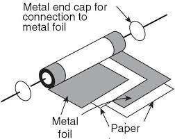
Fig. 4 Paper capacitor
It is most widely used capacitor
because of it’s low cost and broad range of capacitance value (500pF to 50µF).
It can withstand high voltage, however the leakage current of paper capacitor
is high and tolerance is relatively low therefore restricted for some applications.Paper
capacitors are generally used in certain power supply and transmitting
circuits.
3. Plastic film capacitors- Plastic
film capacitors are constructed in the same technique as paper capacitor,
except that a thin sheet of plastic (such as Mylar, Teflon, or Polyethylene) is
employed as dielectric. This dielectric material improves the properties of the
capacitor by minimizing leakage currents at high temperature as 150-200degree
centigrade. Other properties are similar to those of paper capacitor but the
cost is high, generally used when paper capacitor cannot meet the design
specifications. The range of capacitor is between 500pF to 10µF. Fig. 5 shows
the image of Plastic film capacitor.

Fig.
5 Plastic film capacitor
4. Electrolytic capacitors- Electrolytic
capacitors are shown in Fig. 6. The basic structure of aluminium electrolyte
capacitor consists of two aluminium foils, one of which is coated by an extremely
thin oxide. The oxide is grown on the metal by a process of applying a voltage
to the capacitor called forming.

Fig.
6 Electrolytic Capacitor
The thickness of
oxide depends on the forming voltage. Between the foils is an electrolyte
solution soaked into the paper. This electrolyte is a conductor and serves as
an extension of the non-oxidized metal foil. The two oppositely charged plates
are effectively separated by only an extremely thin oxide film which possesses
extremely high dielectric constant. Once the oxide is formed, the foils are
rolled into a tube and the piece of foil without the oxide is connected to the
capacitor’s exterior package which is the negative connection to the capacitor.
The other lead marked as positive terminal.
It
is important to give strong emphasis on polarity connections and rated voltage
must not exceed the limit. It is available in various ranges as 1µF to 0.5F.
5. Non-polarized capacitor- These
are the capacitors which has no polarity constrain issue, it can be connected
either way in the circuit. Fig. 7 shows the image of non-polarized capacitor.

Fig.
7 Non-polarized capacitor
6. Ceramic capacitor- Ceramic
capacitor is the most frequently
used capacitor. It uses ceramic material as insulating material. Ceramic
capacitors are of disc or tubular type. Fig. 8 shows the appearance of ceramic

Fig.
8 Ceramic Capacitor
It
is divided into two types as low loss low dielectric constant, which has high
leakage resistance used in high frequency applications almost as mica capacitor
is used. Second type is low loss high dielectric constant type provides large
capacitance in small volume but capacitance varies as temperature, voltage and
frequency varies, so used in the places where exact capacitance is not required
like circuit coupling and bypass capacitors.
FAQ
1) What
are various types of capacitors?
2) What
is capacitor?
3) On
what category we can classify capacitors?
4) What
is the symbolic representation of capacitor?


0 Comments